
Addbase3dmodel
Start creating
English

Print preparation

A maker’s guide to how to add base to 3d print projects

A base can help a figurine stand, give a display piece a finished edge, or provide a wider footprint for printing. Start with the model’s contact points, then check the combined geometry in your slicer before committing to a print.

Check available tools at the destination
3D model and base design imagery

The audience’s existing pipeline

Most makers already have a model and a slicer. The base belongs between those stages: it must fit the geometry you have and remain printable after export.

Miniature painter

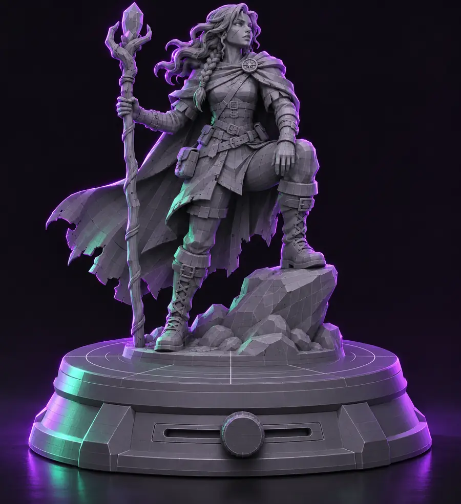
A character balances on narrow feet and needs a display surface that suits its pose. Identify the feet’s contact areas before choosing a round, oval, or shaped plinth; an attractive rim cannot compensate for a disconnected joint.

See add base 3d model examples for ways to match a base outline to a subject.

add base 3d model examples

First-time modeler

A downloaded mesh looks complete on screen, but its underside is uneven. Inspect the bottom view and decide whether to repair the mesh, add a separate platform, or join both into one printable object.

Use add base 3d model tutorial for beginners for a more detailed modeling walkthrough.

add base 3d model tutorial for beginners

Prototype maker

A tall enclosure mock-up needs a stable footprint for a desk review. Check whether widening the permanent base changes the intended dimensions or blocks a connector before altering the design.

Review how do I add a base to a 3d model for the core joining and inspection decisions.

how do I add a base to a 3d model

Slicer-focused printer

A part tips during preparation, and a raft seems like an easy fix. Decide whether the object itself needs a lasting base or whether temporary bed-adhesion features are sufficient for this print.

Read how to add base support in bambu studio to separate model geometry from slicer settings.

how to add base support in bambu studio

Where we slot in

Treat base design as a modeling decision, not a substitute for the slicer’s printability checks. Addbase3dmodel helps frame the design task; confirm the destination’s available tools before relying on a particular operation.

  1. 1

    Inspect the existing model

    Check the underside, intended upright orientation, and points that should touch the base. Record any dimensions that must stay unchanged, such as a connector opening or a miniature’s scale.

  2. 2

    Design the contact and outline

    Choose a base shape that supports the model without hiding important details. Bring the model and base into contact in your modeling workflow, then inspect the join from the side and underneath.

  3. 3

    Validate before printing

    Export through a compatible workflow and open the result in your slicer. Preview the layers, verify that the underside sits on the build plate, and look for gaps or unexpected isolated regions.

Before/after

Use this visual comparison as a shape reference, not as proof that one pictured file was automatically converted into the other.

Base-design studio preview used as an illustrative starting reference Review the starting geometry
Square plinth design used as an illustrative base reference Plan a printable plinth
The meaningful change is not just a wider silhouette: the model must meet the base, the underside must sit as intended, and the sliced layers must show a continuous printable result.

A base does not repair every mesh

Adding geometry cannot automatically resolve holes, inverted faces, or disconnected shells elsewhere in a model.

Workaround

Run a mesh inspection and repair defects before the final export.

A wider footprint is not a print guarantee

Overhangs, material behavior, bed adhesion, and print orientation still affect whether a part succeeds.

Workaround

Inspect the slicer preview and test a small print when the design is uncertain.

Permanent bases differ from temporary aids

A modeled plinth remains part of the object; a raft, brim, or support structure serves a different purpose during printing.

Workaround

Choose the permanent shape for the finished object and configure temporary aids in your slicer.

Destination controls need checking

This guide does not establish which import, mesh-editing, or export controls are available at the linked 3D studio.

Workaround

Check the destination’s current capabilities and use a compatible modeling tool for any missing operation.

Deliverable spec

Compare the model you started with against the result you should inspect before slicing. These are validation targets, not claims about an automatic output.

Starting model
Model with planned base

Footprint

Starting model

May rest on narrow or uneven contact points

Model with planned base

Base outline is chosen for the subject and intended placement

Contact

Starting model

Bottom surfaces may not meet a common plane

Model with planned base

Contact with the base is inspected at every intended joint

Underside

Starting model

May be curved, open, or unsuitable for the build plate

Model with planned base

Base underside is checked in the intended print orientation

Geometry

Starting model

May contain separate shells or existing mesh defects

Model with planned base

Joined result is checked for gaps and unwanted isolated regions

Dimensions

Starting model

Original size and clearances define the constraints

Model with planned base

Added height and width are measured against those constraints

Slicer preview

Starting model

May reveal poor contact or an unstable first layer

Model with planned base

Layers are reviewed for a continuous base and expected model details

Explore a base concept before you print

Take a clear description of your model, its contact points, and the base shape you want to the linked 3D studio. Check its current capabilities there, then validate any geometry you create in a slicer before printing.

Explore base design
  • Describe the intended footprint
  • Preserve critical dimensions
  • Inspect the sliced result

Scenario FAQ

Choose a permanent base when the finished object needs a display plinth, a defined mounting surface, or a wider built-in footprint. If the concern exists only while printing, inspect bed-adhesion and support options in your slicer instead.

If they are intended to print as one piece, check that their geometry meets properly and that the slicer shows the expected connected layers. Separate pieces can also be printed for later assembly, but that requires a deliberate fit and attachment plan.

A base can provide a new flat underside, but it does not automatically repair damaged or disconnected mesh geometry above it. Inspect the join and the full sliced preview rather than judging only the model’s appearance in a viewport.

A modeled base is part of the intended object and normally remains after printing. A raft is a slicer-generated printing aid that is generally removed, so it should not stand in for a display or mounting design.

Verify its dimensions, place the model in the intended orientation, and examine the first layers and the model-to-base contact in your slicer. For a complex or important piece, a small test print can reveal fit and adhesion problems before the final print.

Open 3D studio Start creating